But these remained just interesting ideas to some for propulsion, because there was no power source until the practical development and application of the steam engine in the mid 1800’s. The paddle wheel was the first used to get the engine’s power to the water. The invention of the modern propeller is attributed to Smith and Eriksson, who, in 1835, got a patent for a propeller. A rotating, bladed wheel was shown on Eriksson’s patent drawings. This is seen as the beginning of the development of modern propellers. Early propeller driven steamships were also rigged for sail. One of the earliest, the Lucy Miller, left her prop in Maine for posterity. Bound for Yarmouth, N.S. from New York with general cargo in June of 1893, the Lucy Miller confused Petit Manan Light off Milbridge, Maine for Nash Island Light further east. Her fate was sealed on the already–crowded-with-wrecks, ledges surrounding Petit Manan. The wooden hull of the sail/steamer broke up and the enormous engine dragged her to the bottom. More than 100 years later the eight-foot diameter prop was found, two blades broken off, the other two damaged. The crude cast iron blades—thick, heavy, blunt and nearly flat, have practically none of the finely shaped characteristics of the modern propeller. The bearing was lagged to the wood keel with lag bolts that seem tiny compared to the massive propeller. In the beginning these devices were crude and there were many problems to be solved. The heavy vibration from the way out of tune blades rattled apart wooden ships. With the shaft and engine below the water line, stuffing boxes had to be developed to prevent leaks, thrust bearings and tougher metals to deal with the force had to be developed. Working out these problems produced the ancestor to the modern propeller. While the modern high tech propeller still embodies some of the rotational characteristics of an oar in action, there’s a lot more that didn’t meet engineers’ eyes until fairly recently. Larry Kindberg is a guy who is “into” what makes a propeller work. For most people, the more you dig into what it is that makes this taken-for-granted, apparently simple device do what it is supposed to do, the more they realize how much they don’t know. Ask Larry what makes a propeller propel and you’ll think you’ve died and gone to MIT. His Accutech Marine Propeller in Hampton, New Hampshire looks like a cross between an engineering lab and the orderly quality control department for the space program.
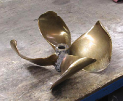
Today props are made of bronze, various bronze alloys and synthetics. To date the largest synthetic prop is about nine feet in diameter. That’s a big prop, but a Russian shipyard recently built a 29-foot diameter prop for a tanker. One model carved out of wood or metal. That has the outline of the blades—the bulged out, curved aft facing surface, and the flatter suction surface facing that faces the bow. The model is pressed into sand and resin, and then, when hardened, a two piece “clamshell” mold is made. The cavity it forms in the sand can be filled with molten metal. The complex process of machining and boring the shaft hole in the hub has been made faster and much more accurate by Computer Numerical Calculation. Computer driven machines make all the cuts on the hub and blades. Similarly shaped blades on a hub, is basically not a lot different from what was done with the Lucy Miller’s prop when the ship was built in 1878. But that is where even vague similarities clearly end. The blades function in water like an airplane wing in air. Water travels faster over the curved aft surface creating thrust. Modern propellers operate at high RPMs, driven by a wide range of powerful engines, on a wide range of hull shapes and loads. All of these factors are considered when choosing a prop for a boat. A choice not easily made. There is no fixed formula, but a melding of high tech science and “rule of thumb.” Dave Gerr’s “The Propeller Handbook,” could be called the propeller bible for practical purposes. In it he writes, “…all propeller selection is a process of approximation and estimation. There are charts and formulas available, but the degree of real-world accuracy you can achieve is limited. The interactions of the water, propeller, and hull with each other are so complex that no one really understands exactly what is happening.” That may level the playing field for some, and put the lights out on the field for others. In very recent years computers have been used with measuring devices to gauge how far from the engineering specifications the surface of a propeller blade, used or new, actually is.
For tuning propellers there are four levels of accuracy. The highest is usually only met for racing propellers. An accurately tuned propeller increases speed and fuel efficiency by at least 10% for both. Racers are finding their way to Kindberg. Galen Alley got props for the Stella Ann and his new boat there. The Cynthia and Lynn won at Boothbay on June 16 running one of Kindberg’s new “four blade series.” The progress that enabled propellers to get hulls up and planning at high speeds came with another set of problems. Early on in the development of higher speed propellers cavitation was a problem. It still is, but it is better understood. Cavitation is low pressure on the suction side of the blade. Water boils at a lower temperature as pressure drops. Cavitation produces boiling without heat but the bubbles break down into small donut shapes. Water spins around the outer edge and down through the donut hole at high speed creating a water jet that erodes metal. Propellers designed to cavitate are therefore made of stainless steel to reduce erosion. The pitch of a propeller is a measurement of the angle of the blade to the shaft. The number value of the pitch is the distance, in inches, that the hull is supposed to be moved by each revolution of the blade. A 24-pitch prop, in theory, moves the hull 24 inches with each revolution. But the propeller is moving in a liquid medium, not a soft wood, and there is slip. Derr describes slip as “the difference between the distance a boat actually travels through the water and the theoretical distance it would travel if it advanced the full pitch of the propeller.” Tides, currents and winds also affect this liquid medium. Pitch is a measurement relative to other degrees of pitch, keyed to many other factors. At New England Propeller, they have worked on props since 1934. One of the employees has a 50 year perspective that runs from the era of a handful of propeller options to a huge range made possible by CNC equipment. Their shop still uses pitch blocks on about half their repair jobs. The blocks were “the” way props were accurately repaired until the fairly recent development of computer driven measuring devices. A damaged or out of tune prop is placed on the solid, heavy steel pitch block and driven against the surface to reshape the prop blades. Badly damaged blades are heated and pressed against the pitch block. They also use computer driven devices to measure the props they work on.
Without knowing this, it comes as somewhat of a jolt—after going through Kindberg’s shop with the five figure decimal specification charts on the walls, dial indicators and computers, blades with 25 measurement points marked off on them, others set up on equipment that looks like an operating table—to learn that the actual adjustments will be done with a hammer. Yeah, a nice looking brass headed hammer, but a hammer. Kindberg says, “This is the art form part, knowing how far to move the metal. You can’t always see it move, the movement has to be felt.” Software, computer modeling and related measuring devices now make the movement of the metal more informed. There are specifications and tolerances for every blade. There are more to choose from every day. Mark Dickenson at Nautilus Marine Fabricators in Trenton, Maine has been sizing propeller for a few years. His shop does a lot of commercial boat fabrication, but a lot of yachts as well, in particular, for Hinckley Yachts. He sees unusual props for specific purposes like the seven bladed motor yacht prop with very narrow blades. All kinds of performance characteristics can be built into a prop. Mark described, though he hasn’t had one in the shop yet, a prop blade for a nuclear sub marine. Those blades are at a skewed angle to the shaft, in the shape of a seals flipper. These propellers are designed to run very quietly. Propeller sizing accuracy involves the consideration of a stack of factors that computers have made easier, if not possible, to evaluate. All boats are propped to their red line rating. Horsepower, RPM rating and speed are coordinated to produce maximum efficiencies. A small overlooked difference in the power train can get the wrong prop on a boat. Kindberg cited a case where a gear ratio for a boat was described as a 1.5:1, so a 26” prop was used. But the boat didn’t run properly. The ratio, it was discovered, was actually 1.45:1, but it was generally referred to as a 1.5:1. The difference of .05:1 translated into changing to a 24” prop, which made the boat run as designed. Vibration is the most common reason props are brought in. Making props on CNC equipment has made it possible the get rid of vibration. Technology will likely take more of the inaccuracies out of prop making, tuning and sizing. It will also integrate a much more complex web of information into the mix that produces these more precise products.
|